Fan wiring tutorial series - How to wire the third generation EC fan?
Hello, welcome to Sherry’s Fun Fan Classroom. Follow our technical engineer to understand the wiring method of the third generation EC fan today.
The third generation EC fan is characterized by a unified hardware interface. Customers can change the I0 configuration according to needs, which is conducive to modularization and standardization. The fan can also be restored to its factory settings.
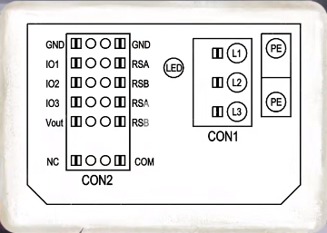
Taking K3G450 as an example, the ground wire is connected to PE, the L1, L2, and L3 ports are connected to the three-phase AC power supply, and the IO2 and GND ports are connected to the analog o-1oV or PWM control signal to control the fan speed. According to the communication protocol, the fan can be set In sensor mode, when controlled by communication, both IO1 and IO2 ports can be used as feedback sources for the sensor.

The corresponding EC control settings are as follows. When analog input control is used, the IO1 port can be used as the control source, and the IO2 port can be used as the feedback source of the sensor, or the two are interchanged. The corresponding EC control settings are as follows. The IO1 port is not wired, the fan is enabled and operates normally. The IO1 port is connected to high level, the fan is disabled and stops running. The analog quantity 0-10V is output between the IO3 port and the GND port to feedback the fan speed. The RSA RSB port is connected to EC control components or third-party communication software for modifying parameters, controlling or monitoring fan operation.
After powering on, the Vout terminal outputs 10V DC, which can be connected to the IO2 port with a potentiometer to achieve stepless speed adjustment of the fan. It can also be used with the IO1 port. The COM port and NC port are relay outputs to feedback fan faults. Among them, COM is the common terminal and NC is the normally closed contact. When powered on, both ends are connected. When the power is off, both ends are disconnected. When the fan is powered on, the IO1 port is not connected. The IO2 port can control the fan speed. The IO1 port is shorted to the Vout port and the fan stops.

 English
 Français
 Deutsch
 Português
 Español
 русский
  한국어
한국어 العربية
 Italiano
 Indonesia
 Schweiz
 Polski
 Nederlands
 ישראל - עברית
 Perzisch
 ไทย
ไทย 日本語
日本語 ኢትዮ-አማርኛ
 Việt Nam
 Kiswahili
 Srpski
 Ελληνικά
 简体中文
简体中文 whatsapp


