
 English
 Français
 Deutsch
 Português
 Español
 русский
  한국어
한국어 العربية
 Italiano
 Indonesia
 Schweiz
 Polski
 Nederlands
 ישראל - עברית
 Perzisch
 ไทย
ไทย 日本語
日本語 ኢትዮ-አማርኛ
 Việt Nam
 Kiswahili
 Srpski
 Ελληνικά
 简体中文
简体中文How to Wire PWM Speed Regulation?
 In modern industrial cooling systems, particularly for Variable Frequency Drives (VFD), most DC cooling fans with speed control use PWM (Pulse Width Modulation) technology. PWM offers precise speed adjustment, high efficiency, and excellent reliability.
Standard 4-wire PWM fans are widely used for intelligent VFD cooling. Typical wire colors and functions (always verify with the datasheet):
Black — GND (Ground)
Red — +12V (Power Supply)
Yellow — Tachometer (Speed feedback signal)
Blue — PWM Control Input
Simple Wiring Steps:
(1)Connect Red (+12V) to a stable 12V DC power supply.
(2)Connect Black (GND) to ground (ensure common ground with the controller).
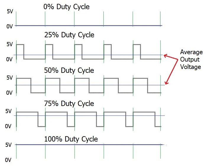
(3)Connect Blue (PWM) to the PWM output of your controller, PLC, or VFD board (25 kHz recommended, 0–100% duty cycle).
(4)Connect Yellow (Tach) to a monitoring input for real-time speed feedback and alarms (optional but recommended).
Important Notes:
The PWM pin is a logic-level signal — do not apply 12V to it.
If the PWM wire is left unconnected, most fans will run at full speed.
Keep PWM signal wires short and away from power lines to reduce interference.
With nearly 20 years of expertise in industrial fan solutions, Beijing Hengrui offers a wide range of high-quality PWM cooling fans with reliable performance and strong stock availability. We also provide stable alternatives for discontinued cooling fan models.
Need help selecting the right PWM fan or wiring guidance? Contact us with your fan model or application — our team is here to support you.Reach us directly via WhatsApp or social channels on the right for quick response, stock check, and model support.
 whatsapp


