
 English
 Français
 Deutsch
 Português
 Español
 русский
  한국어
한국어 العربية
 Italiano
 Indonesia
 Schweiz
 Polski
 Nederlands
 ישראל - עברית
 Perzisch
 ไทย
ไทย 日本語
日本語 ኢትዮ-አማርኛ
 Việt Nam
 Kiswahili
 Srpski
 Ελληνικά
 简体中文
简体中文EC Fan Control Panel Design Protection, Feedback and Modbus
EC Fan Control Panel Design: 3-Step Approach
01 — PROBLEM | EC Fans Are Not Conventional Motors
An EC fan integrates electronic control inside the fan assembly. Traditional contactor + thermal overload logic may therefore not represent the correct protection or control approach.
02 — SOLUTION | Design Around the Fan Interface
Start with the actual fan model and define its power supply, upstream protection, control input, feedback, and communication requirements.
03 — KEY RULE | Check the Fan Manual First
The fan model number alone is not enough. Electrical and communication interfaces can vary between models and configurations.
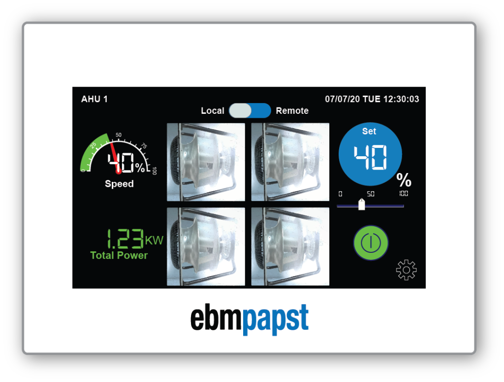
When multiple EC fans are used in an AHU, Fan Grid, or ventilation system, the control panel is more than a power distribution box.
The designer must consider electrical protection, fan control, operating feedback, communication, and BMS/PLC integration as one system.
The key difference is simple: an EC fan has integrated electronic commutation and drive electronics. Therefore, conventional motor-control logic should not be copied directly.
Design note: Circuit breakers, upstream protection, control signals, and communication settings must always be verified against the specific fan manufacturer's documentation and applicable local electrical codes.
Why Is EC Fan Control Panel Design Different?
A conventional motor system can often be simplified as:Control Panel → Motor Starter → Motor
For an EC fan, the architecture is closer to:Control Panel → Upstream Protection → Integrated EC Electronics → Fan Motor
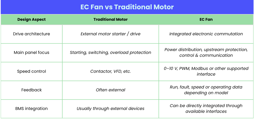
Pic.1 EC Fan vs Traditional Motor
Circuit Breaker and Protection: What Should Be Checked?
One common mistake in EC fan MCC design is selecting the circuit breaker based only on the fan's rated current.
EC fans contain electronic components, so their input characteristics and protection requirements may differ from conventional motors.
Before selecting upstream protection, check the following:
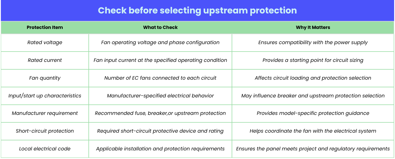
Pic.2 Check before selecting upstream protection
The important distinction is that integrated fan protection does not mean upstream electrical protection can be omitted.
At the same time, designers should not automatically copy the conventional contactor + thermal overload relay architecture used for standard motors. The correct approach is to follow the EC fan manufacturer's electrical documentation and coordinate it with the overall panel design.
AHU Fan Feedback: What Does the BMS Need to Know?
Control and feedback are two different functions.
A BMS may send a speed command to an EC fan, but that does not necessarily tell the BMS whether the fan is actually running at the expected condition.
A useful principle is:A command tells the fan what to do. Feedback tells the control system what the fan is actually doing.
Depending on the EC fan model, available interfaces may include:
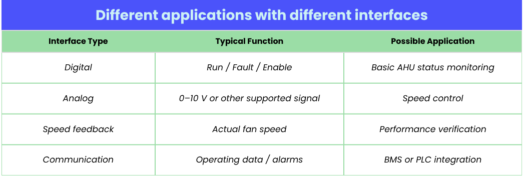
Pic.3 Different applications with different interfaces
A command tells the fan what to do. Feedback tells the control system what the fan is actually doing.
Do EC Fans Need CT Monitoring?
Not necessarily.
Current transformers (CTs) can be useful when the project requires independent electrical monitoring, such as:
However, CT monitoring may be unnecessary if the EC fan already provides the required operating data through its communication interface and the project only needs basic run/fault information.
Therefore:CT monitoring should be driven by the monitoring objective, not simply by the presence of EC fans.
Before adding CTs to every fan circuit, determine what the BMS actually needs to measure.
Modbus for Multiple EC Fans: What Should the Control Panel Designer Check?
When an AHU or Fan Wall uses multiple EC fans, Modbus can simplify communication between individual fans and the BMS or PLC.However, the communication architecture should be defined before panel wiring and commissioning.
The key point is that monitoring, control, fault reading, and fault reset are not necessarily the same function. Their availability and implementation depend on the specific EC fan model and manufacturer documentation.
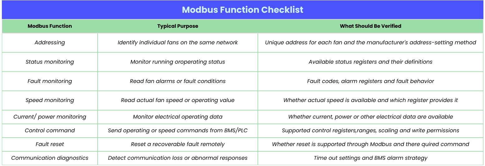
Pic.4 Modbus Function Checklist
A Critical Point: Fault Reading ≠ Fault Reset
One common mistake in ebm-papst Modbus or other EC fan communication projects is assuming that if the BMS can read a fault, it can also reset that fault.
These are separate functions.
A specific EC fan may support fault monitoring through Modbus but require a digital input, power cycle, manual intervention, or another defined procedure for fault reset.
Therefore, the control panel designer should verify these functions individually before finalizing the PLC/BMS logic.
EC Fan Control Panel Design Checklist
Before releasing the control-panel design, confirm:
The most important principle is:
Do not design the panel from the fan model number alone. Confirm the complete electrical and communication interface first.
Conclusion: Design the Panel Around the Fan Interface
For an AHU, Fan Wall, or multi-fan ventilation system, EC fan control panel design can be simplified into three questions:
1. How will the fans be powered and protected?
Getting these three layers right can prevent problems during panel manufacturing, installation, commissioning, and BMS integration.
Need Support for an EC Fan Control Panel Project?
Planning an AHU, Fan Wall, or multi-EC-fan control panel?
Send us your fan list, quantities, electrical requirements, and control/BMS requirements.
Hengrui can support fan selection, electrical interface confirmation, feedback requirements, authorized supply, and Modbus integration planning—helping your team confirm the right fan and control architecture before procurement and commissioning.
Contact Hengrui for technical selection and project support.
 whatsapp


